Discussion
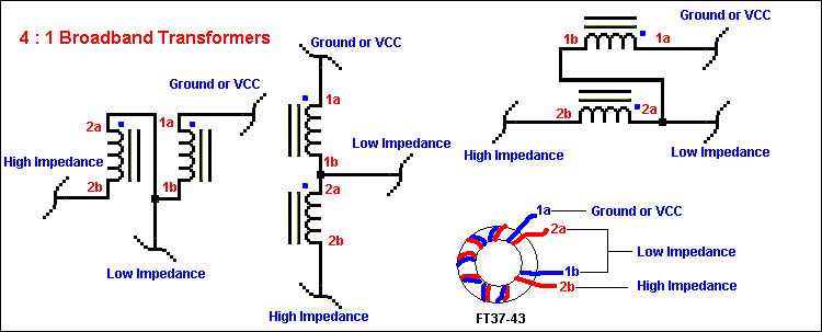
There are 2 basic types of broadband transformers used in most QRP work, conventional and transmission line style. Both types can be wound on ferrite toroids, potcores or rods, however for this discussion we will confine ourselves to the toroidal types used to give a 4:1 impedance transformation. These transformers are used throughout the various projects on this website. For MF and HF uses, a ferrite core permeability of 850-900 is generally required and the FT37-43 ferrite core is suitable. This will allow AC circuits to transform from unbalanced 50 ohms impedance up to 200 ohms unbalanced impedance or visa-versa. Shown below are three equivalent schematics of the 4:1 transmission line transformer. The center drawing is the easiest to conceptionalize, however close examination will show that all 3 schematics represent the same thing. The high impedance is 200 ohms and the low impedance is 50 ohms in all cases. It is important to know that these transformers are symmetrical and the points labelled Ground or VCC can be switched with the point labelled High Impedance. There are a great many published references on RF transformers for further study.
These transformers are wound as bifilar (2 wires) which are generally
twisted together. Winding these transformers is very easy. All that is required
is two 7 to 8 inch pieces of #28 AWG enamel coated wire and an FT37-43 ferrite
toroidal core. A vise, ruler and a brace and bit drill are also very useful. I
got my brace and bit drill at a garage sale for two dollars. You need to twist
the 2 pieces of wire together so that there is around 8-10 twists per inch in
the wire. To do this, loosely twist the wires at one end so they are of equal
length. Place the twisted ends in a vise about 1/4 inch. Next, place the free
wire ends together in your brace and bit drill chuck (no drill bit) and tighten
up the chuck so that the wires are held secure. The wires should be of equal
length and tension. Start hand winding the drill to twist the wires together and
every once and a while use the ruler to check how many twists are in a one inch
space. When you get to 8-10 twists per inch you are done and can trim the very
tips with a wire cutter in preparation for winding.
Winding the 4:1 Transformers
You generally need
somewhere ~ 7 inches of wire for winding a complete transformer. Leaving a 1
inch lead, wind ten complete loops through the toroidal core leaving a small gap
between the start and finish leads.
Untwist the leads a little so that you
have 4 seperate wires. One set of these wires wires will be called winding #1
and the other winding #2. You need to identify them and further break them into
1a, 1b and 2a and 2b. Generally I regard the the top two windings as A and the
the bottom two wires B. Use whatever system works for you. Strip off all the
enamel on all four leads and then get your ohm meter or better yet a beeping
continuity tester. Start on one of the top (A) wires by connecting the ohmmeter
or contunuity beeper to it and then touch one of the bottom wires and then the
other bottom wire. Whatever bottom wire shows continuity with the top wire
should be marked along with the source top wire with paint, liquid paper or
whatever you like. Designate the marked wire pair winding number 1. You can test
for shorts as well, there should be no connection between wire set 1 and wire
set 2 at all! So now you have two wires sets, winding set 1 is marked and
winding set 2 is unmarked. The top two wires are arbritrarily labelled A and the
bottom two wires are labelled B . Refer to the diagram above for clarification.
Connect 1b to 2a and twist them together and then solder. Your transformer is
done. It is really easy to make these things.
More elaborate methods
such as using 2 color wire and painting one wire maybe used. These transformers
will also work if the wires are untwisted, when you twist them, 8-10 twists per
inch is a guide only and is not critical. Never use bare wire for these
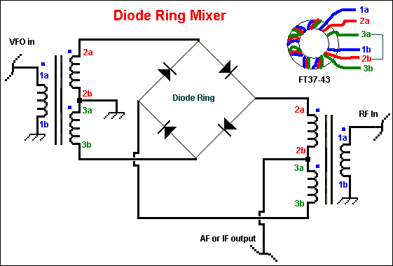
transformers. Homebuilding Diode Ring Mixers

Discussion
Diodes
