 |
|
 |
LATEST UPDATE, November 15, 2003: See title re: Relays HBR-2000 HF 9-band High Performance All-Mode Transceiver This page provides a brief description of the receiver portion of a HF High Performance Tranceiver that I have built. I named it the HBR2000. HBR being short for homebrew and 2000 is the year that I had my first CW QSO with the rig. Todate, I have only taken 2 tone Dynamic Range (DR) and 3rd Order IMD receiver measurements on 20 meters. The MDS measurements on all bands are within + or - 0.5 dB of -132 dBm . All measurements were made with a IF filter BW of 400 Hz. Test oscillators are two seperate xtal osc's which produce 0 dBm output. MDS measurments made with a HP8640B signal generator and a true reading RMS volt meter across the speaker output: Oscillator Spacing 20 KHz 5 KHz 2 KHz
MDS (Sensitivity) -132 dBm
BDR (2 tone Blocking Dynamic Range) >122 dB
3rd Order IMD Block Range 102.5 dB 99 dB
Third Order Intercept (IP3) +23.5 dBm +22.25 dBm +14 dBm
Image rejection all bands >135dBm
Tansmitter specifications are: CW/SSB 160 to 10 meters, 9 watts output, full QSK on CW. A 100 watt amplifier is housed in a separate encloser along with the power supply. The final amplifier incorporates a single MRF151 power FET running on 48 volts. It is followed by separate diplexers and elliptical LP filters for each band. All harmonics and image products are 55 db or more below the carrier level. Front Panel View  For many years I dreamed of building a high performance multi-mode HF transceiver. However, priorities such as family and work left little time to take on a major project like the HBR2000. In my early years as a ham radio operator, I built several Heathkit tansmitters and transceivers and later as I gained experience I began homebrewing solid state direct conversion receivers and QRP single band transmitters. Approximately five years ago I decided that it was time to stop dreaming of building a high performance transceiver. The HBR2000 is my dream come true. THE DESIGN PROCESS The design process began by deciding on features and specifications that would suite my particular operating style. With other hams in close proximity, the receiver had to have a very strong front end. As well, I often operate in various contests so good selectivity is important. Though I operate mostly CW I still wanted the capability of operating SSB. In addition, being able to listen to AM is a feature that I thought was important. I began by drawing a block diagram of the receiver portion. I broke it into several modules so that I could build one section at a time and then test it before proceeding with the next stage.
Since I am not an electical engineer I am aware of my limitations as far as designing circuits. Why re-invent the wheel when someone else has already gone though the trouble? Therefore, where suitable, I used circuits from various designs that have been published in amateur radio periodicals such as QST, QEX, The ARRL Handbook and books such as, "Solid-State Design for the Radio Amateur" by W1FB and W7ZOI and "Introduction to Radio Frequency Design" by W7ZOI. You may find further information regarding these publications at the following Web site: The latest ARRL technical publication "Experimental Methods in RF Design" by Wes Hayward, W7ZOI, Rick Campbell, KK7B, and Bob Larkin, W7PUA is a must for anyone contemplating the thought of building their own radio equipment. This work is successor to "Solid-State Design for the Radio Amateur" which was first published in 1977. EMIRFD, is 512 pages of fasinating reading and includes a CD-ROM with design software, listings for DSP firmware, and supplementary articles. © 2003, published by American Radio Relay League (ARRL). (ISBN: 0-87259-879-9) #8799 -- $49.95 USD There is a wealth of information in this publication applicable to homebrewers! When I found a design for a section that I liked and a PC board was available I purchased it, otherwise I used what is referred to as "ugly construction". Ugly construction is the process of using copper clad PC board material for a base to build electronic circuits on. Once I had chosen the circuits for each section I asked a friend to look it over and make suggestions and point out things that I hadn't considered. It is a very good idea to be friends with an elmer, i.e. someone that knows more than you and is experienced in not only designing but actually building electronics circuits. THE AUDIO AND DETECTOR MODULE Working from the back to front seemed to be the way to go, so I started with the audio and detector module. I had previously used the R-1 PC board from Rick Campbell, KK7B's article, "High-Performance Direct-Conversion Receivers", in August 1992 QST to construct a DSB transceiver for 6 meters. (see above menu bar for the 6 meter design, DCP-10) For information regarding the High-Performance Direct-Conversion Receiver see; PC boards for the R1 are advertised as being available from Kanga US. For ordering information see; I was very pleased with the audio quality of this design. The PC board also contained room for a double balanced mixer intended for a product detector. Since I was including the capability to receiver AM, I added transistor switches to select between the product detector and the AM detector. For the BFO I used diode switched crytals to cover, USB, LSB, CW lower and upper sideband and another one for Digital. The output of the BFO is amplified to provide +7dBm to the product detector, 150 mV to the tranmitter balanced modulator and a low level output for the frequency counter. Once the Product Detector Audio board and BFO circuits were completed I injected a signal into the Product Detector and checked to make sure all the crystals were oscillating, trimmed them to the correct frequency and then checked the audio circuits for linarity. Since the audio gain of the R-1 audio board is higher than needed I lowered the gain of the op amps preceeding the final output audio output transistors. This module is inclosed in a box made of PC material with all leads going in and out fed through feed-thru insulators except for the input from the IF stage where I used a BNC connector. THE IF MODULE In the May 1996 issue of QST, Bill Carver, K6OLG, presented "A High-Performance AGC/IF Subsystem". The specifications for this system are impressive so I ordered a PC board from Far Circuits. The board is still listed as being available. See the following site for ordering information: After building the IF system and powering it up to confirm that it was working, I built a box made of PC board to house the IF system. The 43 pf cap. in parallel with the primary of T-2, an 8 turn trifilar winding, will not resonate at 9 MHz as indicated in the QST article. I used a 180 pf cap. across the primary of T-2 to resonate at my IF frequency of 8.83 MHz. The IF is very sensitive. I measured the MDS at -138 dBm looking into the JFET pre-amp with a 2.5 kHz BW filter mid way through the IF module, this caluclates out to be a NF of 2 dB. When inclosed inside the PC box, the IF module oscillates vigorously. Even after applying judical grounding I needed to place a shield made of thin guage copper over top and around the first two stages to stop the oscillation. Feed-thru insulators were used for all leads going in and out of the box except for the RF lines which use BNC connectors. The AGC system is superb, no thumping, clicks or distortion even when listening to really strong signals. I really appreciate the "Hang On Transmit" feature of this particular design. While working fast VOX SSB or QSK CW with AGC setting set to fast recovery, between pauses in your voice or CW characters, the IF gain does not immedialty increase to full gain but reverts to the gain level determined by the AGC circuit just before transmission started. This is especially appreciated while operating on bands such as 160 and 80 meters where the back ground noise is sometimes considerably higher than the higher HF bands. You have to hear it to believe it. The next picture shows the IF stage, notice the shield over the the input JFET and first IF amp IC. 
IF FILTERS I had several Kenwood 8.83 MHz cyrstal filters on hand and decided to use them in the receiver. I again built a box of PC material this time to house the crystal filters. I use relays instead of diodes to switch between the different filters as I did not what to chance introducing IMD via diodes into the receiver. The BW of the filters I had on hand were, 6kHz, 2.5kHz, 1.8kHz, 400Hz and 250kHz. A shield was inserted between the input and output terminals of the fitlers to increase the stop band attenuation. Again all control leads go through fed-thu insulators and the input and output RF points employee BNC connectors. FREQUENCY CONTROL Since low oscillator phase noise is one of the pre-requisites to obtaining a high overall receiver dynamic range, I decided to use an analog VFO and mix the output of the VFO to the required injection frequency with separate crystal oscillators for each of the 9 lowest amateur radio bands. The VFO tuning range is 1 MHz. I can thus tune from the low end of 20 meters up to WWV at 15MHz. As well, a 1 MHz tuning range allows me to cover the lowest 1 MHz of ten meters without having to build another crystal oscillator. The VFO power output level is set to -10 dBm and the crystal oscillators to +7 dBm. An analog VFO is considered by many as old technology, however it is much easier to make a clean, low phase noise analog VFO than a digital VFO. Technology is improving daily and no doubt it won't be long before you will be able to purchase a single IC that will do the job of an analog VFO with similar spec's but until then, the analog VFO is still king! The VFO is filtered with a 2 section LP filter to attenuate harmonics. With the HBR2000, I can tune to within a couple of kHz of a local ham before knowing he is there. I have not been able to do this with any of the commercial ham radio transceivers that I have had the opportunity to compare to the HBR2000! Here is a picture of the inside of the HBR2000. The xtal. osc. boards and mixer are to the left, the BPF's in the middle and the transmitter box is folded towards the back lying on top of the receiver Mixer, IF and Audio boxes. The frequency counter is to the right with the VFO underneath. Below the frequency counter standing upright is a box housing the noise blanker TRF receiver. The transciever is built so that each section can be either folded out and away from the main tranceiver chassic or easily removed for testing and maintenance purposes. 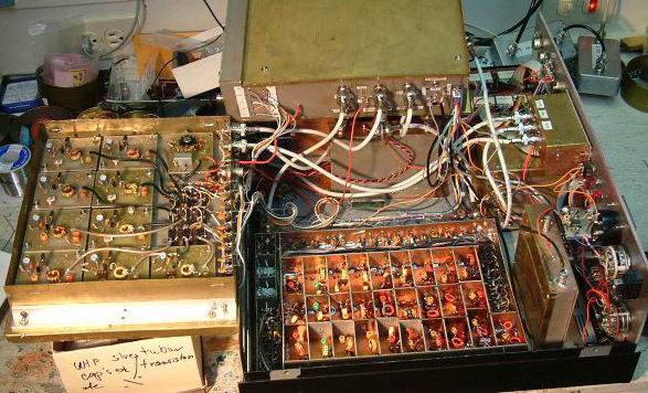
The VFO and Crystal oscillators are fed into a double balanced diode mixer and then filtered by 9 separate relay switched 2 section Series C BPF's (bandpass filters). Some may question the wisdom of using only a 2 section filters at this stage however, the receiver input BPF's (which are also shared with the transmitter) are 3 section filters and provide adequate stop band attenuation. After filtering, further amplification increases the LO power output where it is split into three separate outputs, +17 dBm for the receiver mixer, -5 dBm to the transmitter board (later to be amplified to +7 dBm for the transmitter mixer) and a low level output for the frequency counter. When I first built the LO system I did not pay attention to setting the VFO ouput level and for reasons I can't remember, the VFO output was 0 dBm. After connecting the LO to the receiver mixer I found a number of spurs that shouldn't have been there. Wes, W7ZOI came to my rescue explaining the importance of not driving the RF port of a balanced mixer with more than -10 dBm. After decreasing the VFO output to -10 dBm the spurs disappeared. The VFO is built into a box made of PC board material. The 9 crytals oscillators and LO mixer are built into the top half of a box made of PC material. The bottom half of the box contains the 9 BPF's and an amplifier to boost the LO output power to the desired level. FILTERS Filters, play an important role in the development of high performance receivers and transmitters. The HBR2000 contains over 30 separate filters. One test instrument that I found invaluable is the L/C Meter kit produced by Almost All Electronics Inc. This instrument allows the experimeter to quickly determine inductor and capacitor values. When winding toroid coils, I calculated the number turns required for the desired inductance value and then after winding the coil I measured the value with the L/C meter. If required I then squeezed or expanded the turns until I reached the correct value. This process saved many hours of tuning filters after they were built. The L/C meter is also helpful in determining the value of poorly marked capacitors which seems to be all too common these days. You may find information regarding the L/C meter at: This picture shows one of the nine BPF's shared between the receiver and transmitter. The filters are shielded from each other in addition to having shields between each sub section of each filter. 
All the filter component values used in the HBR2000 were derived using a program that my friend developed. See the Design Page on the main menu bar of this Web site for further details. I have found this program indispensable. It contains many other features besides filter design such as, a VFO component calculator, an impedance matching circuit calculator, mixer spurious i mage calculator, an active IC filters design and a Calculator page that has a number of other useful features such as, the reactance of capacitors and inductors, resistive attenuator values, an air coil calculator and receiver noise analysis program. It is easy to use and provides very good quality graphs showing attenuation and input return loss. Below is a copy of the graph produced by the RF Design Program for the 14 to 15 MHz BPF filter that preceeds the receiver mixer in the HBR2000 (filter output [to mixer] is actually on the left to show match to mixer!). The 14.5 MHz series trap matcher (diplexer) terminates the mixer RF port in 50 ohms over a broad frequency range improving the 3rd order input intercept of the receiver mixer.
 Notice that the insertion loss (blue line) of the filter increases more rapidly above the design frequency than below. This provides greater attenuation at VHF/UHF frequencies where local high power TV and FM stations are located. This diminishes the possibility of these out of band signals reaching the mixer and combining with VFO and HFO harmonics and mixer products that could produce unwanted spurious signals in the receiver. This is a picture of the spectrum analyzer screen showing the characteristics of the 14 MHz BPF filter. The left side of the screen indicates an attenuation at 7 MHz (40 meters) of -58 db and the right side is 21 MHz (15 meters) with an attenuation of > -65 dB. Each horizontal division is 10 db. 
For 160 and 80 meters I used Series L BPF's. The insertion loss of Series L BPF's increases more rapidly below the design frequency than above. This helps attenuate local strong AM broadcast stations. At my QTH there is an AM station at 980 kHz which is very strong. The filter I designed has an attenuation at 980 kHz of over 70 db. With a 160 half wave loop tuned for minimum SWR at 1.85 kHz, I inserted the 160 meter BPF between the antenna and my TS940s and tuned it to 980 kHz, I measured attenuation at 68 dB. I have no birdies on 160 or 80 meters caused by AM broadcast stations with the filters I designed for the HBR2000.  All the RF input filters are built inside a box made of PC board material. The box is subdivided into 9 sections, one for each filter with additional shields between each sub-filter section. I have measured stop band attenuation in excess of 96 db with the cover on the filter box. All of the filters in the HBR2000 are switched with relays. Many commercial amateur radio transceivers use diodes to switch between filters. Diodes switches can introduce IMD in the presence of other very strong RF signals. European hams in partiuclar are aware of this problem as 40 meters is also occuppied by really strong AM shortwave stations. RELAY TROUBLES, November 15, 2003 There is a problem associated with using relays to switch very low RF levels. I noticed over the period of several years that some of the relays used to switch the input BPF's did not close completely the moment a particular band was selected. For example, when I changes bands, the receiver antenna noise sometimes was lower than usual say for 10 to 60 seconds and then all of a sudden the antenna noise would rise to the expected level. This was confirmed by looking at the 15 meter BPF with the spectrum analyzer and tracking osc (this band gave me the most trouble). As pointed out by Peter, G3RZP in Letters to the Editor, page 58 in QEX Sept/Oct this problem is associated with oxidation of the relay contacts. This solution is to run a constant DC current through the relay contacts when they are closed. I recently added resistor dividers to pass approx 0.7 mA DC through the input RF filter relay contacts when switched on. Initially this did not solve the problem so I increased the current to 100 ma DC and switched the relays on and off many times (50 to 100 times worked for me) to clean the contacts. After the contacts were clean, I reverted back to the lower current circuit. I no longer have problems with the relays. THE DIPLEXER, MIXER, POST MIXER PRE-AMP and NOISE BLANKER SWITCH The first mixer circuit I employed was a double balanced diode circuit with a LO power of +7 dBm. Wanting to increase the dynamic range of the receiver I changed the mixer to a Mini Circuit TUF-1H which requires a LO power of +17 dBm. The change in mixer and increase in LO power did not increase the IP3 as expected. A double balanced diode mixer with an LO of +17 dBm should be able to produce an IP3 of approximately +23 dBm. I was only achieving +14 dBm. John Stevenson, KD6OZH, wrote an excellant article titled "Reducing IMD in High-Level Mixers" in May 2001 QEX, page 45. He examined how IMD was effected by the match looking into all the ports of high level double balanced diode mixers. He found that having a good match into the RF port was as important as the IF port. In order to acheive a low SWR at the RF port he employed a diplexer between the front end BPF and the mixer. When I inserted a diplexer between my 14 mHz BPF and the mixer the IP3 increased from 14 dBm to 23.5 dBm. I have since added diplexers to all the bandpass filters in the HBR2000. The two tone dynamic range, (tones spaced 20 kHz apart), increased from 93 db to 103 db with the new mixer, well worth the effort. The mixer is followed by a Tee-Bridge Diplexer and a post mixer Pre-Amp after a design by W7ZOI using a 2N3866 tansistor. The gain of the amplifier is 22 dB followed by a 6 db pad to improve the output stage match to the IF filters. Following the post mixer Pre-Amp is a diode switch for the noise blanker circuit which is switched in or out of the circuit with relays. The following picture shows the Mixer, Diplexer, Post IF Pre-amp and relays on the input and output of the blanker diodes. Notice that I have included a shield around the +17 dBm LO input to provide additional isolation from the output port. +17 dBm is a lot of power and it is a good idea to keep it from getting into places it shouldn't be! Good shielding helps to accomplish this. 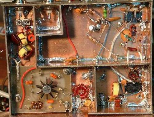

The new mixer scheme performs really well. A local ham now a SK lived only one city block from my QTH. When he operated SSB on 20 meters using high power I could tell he was on the band even though I was listening in the CW portion of the band with my TS940s. The TS940s is known to suffer from recipical mixing in the presence of very strong signals. With the HBR2000, I was unable to tell he was on the band unless I tuned to within a few kHz of his frequency. THE CW Audio Filter There are times when a little extra filtering can make the difference between coping a station or not. Even though the narrowest IF cyrstal filter is 250 Hz wide, I've had experience using a narrow bandwidth audio filter and found it quite effective especially on noisy band like 160 meters. The problem with the narrow bandwidth audio filter is that it is a peak filter design and it rings excessively. I asked my friend to encorporate the ability to design audio filters that have a Butterworth shape hoping that it would not ring as much as the peak filter. If you go to the the Design tab in the menu above and then to active filters, you can use the program to design a fitler to your likeing. Adjusting the bandwidth, centre frequency and trying different capacitor values I was able to come up with an audio filter employing 3 op amps with a BW of 144 Hz centred at the frequency I like listening to, 640 Hz. The resistor values are close enough to standard values that I was able to find the ones I needed by measuring enough resistors to find ones that were within 1% of the design values. The circuit called for 6 capacitors each 0.01 uF and they also had to be accurate to within 1%. I took my capacitance measuring meter with me to a local electronics store and asked permission to go through a bag of capacitors to find the right values. After building the audio filter on a breadboard, I was able to determine that the filter shape matched very closely to what the program predicted. The fitler is inserted between the audio preamp stage and the panel mounted volume control and switched in or out with transistor switches. The Butterworth design still rings a little but not nearly as much as the peaked audio filter. When listening on 160 and 80 meters where there is considerably more noise I find that the audio filter really helps when copying weak CW signals. The following picture shows the finished version of the audio filter built inside a box made from PC board material. Notice the point to point wiring, "ugly construction technique". I turn the IC's and transistors upside down and wire the components directly to the IC and transistor leads. This type of construction lends itself to making changes to a circuit which as experimenters we seem to do quite often. Also it is so much easier to trace a circuit as all the wiring in on top of the board. In hindsight, I wish I had not used any etched PC boards in the HBR2000. To make changes to a particular stage built on an etched PC board, I have to remove the board from the PC box which is a lot of trouble. With ugly construction technique, everything is on top of the board which makes it a simple matter to remove a component(s) and insert new ones. 
TEST EQUIPMENT The following picture shows some of the test equipment I built during the development of the HBR2000. At the bottom is a step attenuator, the box below the scope houses the Spectrum Analyzer based on the W7ZOI/K7TAU design (August 1998 QST) and above the scope is a the Power Meter based on W7ZOI/W7PUA design (June 2001 QST) with digital read out addition by K3NHI (May/June 2002 QEX) 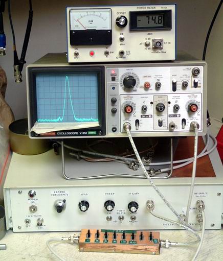
The receiver section of the HBR2000 is an absolute joy to use. There are no unwanted birdies or images, the audio is cyrstal clear, the IF filters are sharp, plus the AGC has to be heard to be appreciated. The many, many hours spent in planning and building have been well worth the while. Sincere thanks to a special friend and "elmer", who wishes to remain anonymous, who gave unselfishly of his time to answer my unending questions and Wes, W7ZOI who offered encourgement, sound advise and suggestions. |