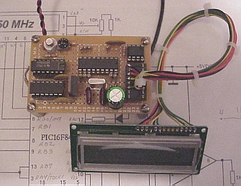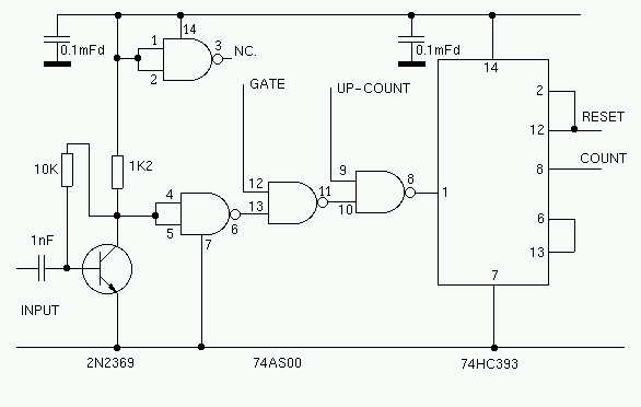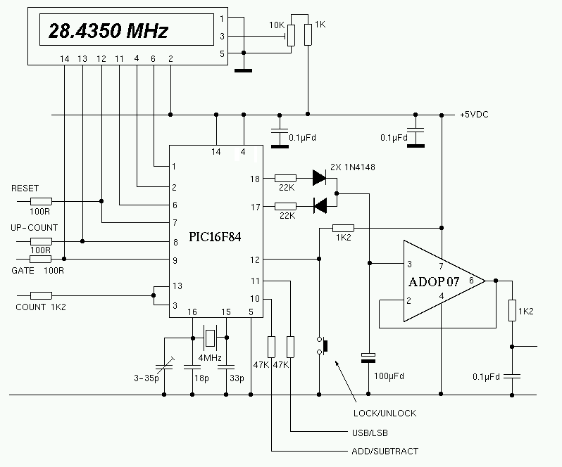


The square wave signal from the first counter is fed to the RTCC (Real Time Clock Counter) input of the PIC. The value in the external counter can not be read directly. A simple trick is used to read the value in the external counter. After the counter gate is closed, the PIC increments the external counter by sending pulses to the secondary counter gate (pin 9 of the 74xx00). By counting the number of pulses required to overflow the counter, it is a simple matter to calculate the value that was in the counter at the time the gate was shut. A similar method is used to determine the value in the PIC internal prescaler. The final (most significant) 8 bits of the count can be read directly from the PIC's internal RTCC register. For more information about the PIC16F84, download the data sheet from: Microchip. When the frequency is stored in the PIC, the IF offset is added or subtracted. This kind of simple arithmetic can be done quickly and easily with a PIC. The binary number is then converted to BCD and sent one digit at a time to the LCD display. This entire process takes just a few milliseconds. Once the count result has been sent to the LCD display, the counters are reset, and the gates are opened for the next count.
When the LOCK button is pressed, the current count is stored in the PIC's internal registers. This value is compared to the next count, and all subsequent counts. If the VFO has drifted, the most recent count result will not be the same as the stored number. If the VFO drifts up in frequency, a negative correction pulse is generated to correct the drift. If the VFO drifts downwards, a positive pulse is generated. The pulses are converted to a slowly changing DC voltage by an op-amp integrator circuit. The choice of op-amp is quite critical. I use an ADOP07CN. A form of PWM (Pulse Width Modulation) is used to give proportional control of the VFO. If the drift is small, a small (narrow) correcting pulse is sent to the integrator. If the drift is large, wider correcting pulses are used. The correcting voltage is applied to a varicap diode in the VFO. The VFO should be arranged so that a DC voltage ranging from 1V to 4V, will shift the VFO frequency by +/- 1KHz.
For a more comprehensive description of the circuit, see: Elektor magazine for Feb. 1998.
gadget40.asm PIC16F84 source code. 7.8MHz I.F.
gadget39.asm Previous version.