Cobra 148 GTL-B
Printed Circuit Board PTBM122DOX
Alignment information for the PTBM122 PCB
Preset to channel 40, mode USB, clarifier centered.
The Mode in brackets ( ) indicates which mode the radio should be
in.
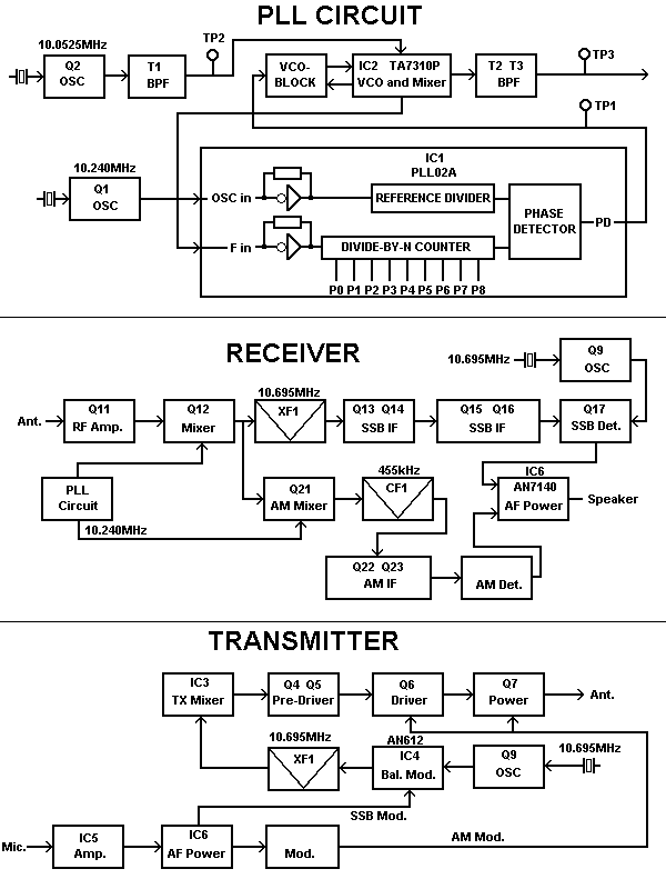
PLL Circuit
| Reading Point | Adjustment | Description | Value |
|---|
| IC1, pin 3 |
- |
Check for 10.240MHz +/- 50Hz |
10.240MHz |
| IC4, pin3 |
CT6 |
(USB) AM/USB Carrier oscillator |
10.695MHz |
| IC4, pin3 |
CT5 |
(LSB) LSB Carrier oscillator |
10.692MHz |
| TP2 (IC2, pin 4) |
CT2 |
(USB) AM/USB offset oscillator | 20.105MHz |
| TP2 |
CT1 |
(LSB) LSB offset oscillator | 20.1035MHz |
| TP3 | T1 | 0utput to RF local oscillator | 37.660-38.100MHz for CEPT |
| TP1 | VCO-Coil |
VCO DC Voltage (DONT ADJUST IF WORKING OK!) |
1.2 Volts @ channel 40 (27.405MHz) +/-0.5V |
Transmitter Circuit
Preset to USB, channel 20, inject 2400Hz, 10mV audio signal.
| Adjustment | Description | Value |
|---|
| T2 |
VCO Mixer Output |
Maximum RF output power / best signal on oscilloscope at TP3 |
| T3 |
VCO Mixer Output |
Maximum RF output power / best signal on oscilloscope at TP3 (check even
on channels 1 and 40) |
| T4 |
Transmitter Output |
Maximum RF power output |
| T5 |
Transmitter Output |
Maximum RF power output |
| L16 |
Transmitter Output |
Maximum RF power output |
| RV4 |
Final Bias (Q7) |
Connect DC Voltmeter to Q7 base (junction of C55, R34, L13) adjust for
0.70V |
| RV13 |
SSB Modulation |
inject 2 tones, 500Hz and 2400Hz, at 10mV, adjust for 12 Watt pep |
| RV7 |
Carrier balance |
Check / Adjust for NO Carrier on both LSB and USB |
| RV15 |
AM Output Power |
Remove injected audio, Adjust for 6W carrier, a lower
power level may be required to attain full modulation. |
| RV14 |
AM Modulation |
Return to single 2400Hz tone @7mV, adjust for 92% modulation (see note
above) |
| RV6 |
RF Power Meter |
Adjust to match actual RF power |
| | |
Receiver Circuit
Preset to channel 20, USB, clarifier centered, NB/ANL turned off, RF gain
set to maximum.
Be ready to inject a RF signal with an RF signal generator.
| Adjustment |
Description |
Value |
| RV8 |
SSB AGC |
?? |
| T6 |
RF Input |
Inject RF signal of 27.205MHz, 1KHz, 30% modulation, (keep the level
low to prevent AGC action), adjust for maximum on radios signal meter /
audio level at speaker (as measured with a scope or AF-VTVM) |
| T7 |
RF Input |
as above. |
| T8 |
RF Input |
as above. |
| T9 |
1.F. |
10,7MHz, as above. |
| T10 |
1.F. |
10,7MHz, as above. |
| T13 |
AM IF |
455kHz, as above. |
| T14 |
AM Detector |
455kHz, as above. |
| T11 |
SSB IF |
455kHz, as above, also set for maximum audio output. |
| T12 |
SSB Detector |
Set for maximum audio output. |
| T6, T7 |
|
turn both approx. 1/4 of a turn clockwise |
| RV10 |
AM S-Meter |
Set RF signal generator to inject a 100uV signal, 1KHz, 30% modulation
signal, adjust for "S9" in radios signal meter . |
| RV9 |
SSB S-Meter |
Remove audio from RF signal generator, set for "S9" on radios signal
meter. |

This counter shows the number of hits since the
3rd July 2004

Go Back To The Alignments Page
Go Back To The Main Home
Page
Copyright © The Defpom 1997-2005
http://www.radiomods.co.nz/

