![[MWA Engineering Dept.]](modulators_files/circuitheader.gif)
![[MWA Engineering Dept.]](modulators_files/circuitheader.gif)
This page copyright 2003 by Medium Wave Alliance. All rights reserved.
Simple AM modulators work by varying the amount of power flowing through the transistor which is serving as the RF output amplifier. By imposing an audio waveform on the power supply, amplitude modulation is achieved.
Rather than giving detailed examples, this page gives simplified schematics, followed by links to circuits that actually use the various techniques.
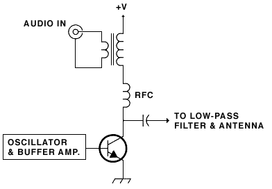
An external audio amp sends its output to the 8-ohm side of an 8-to-1000 ohm (or similar) audio transformer. The other winding of the transformer is inserted in the power supply going to the final RF amp transistor. The audio transformer must be rated to handle the level of power going through it; an inadequate transformer will produce a bad-sounding signal. In some cases it takes a lot of searching and experimentation to find the best transformer.
Examples of technique #1 include the Talking Pixie and the Quest transmitter.
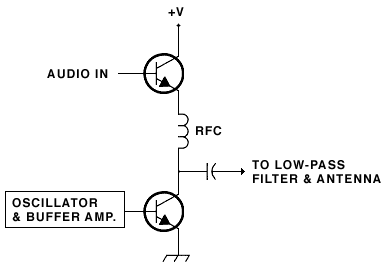
A lightly amplified audio signal is fed to the base of an NPN transistor. This transistor is inserted into the power supply going to the RF amp transistor. A choke between the two transistors keeps RF out of the power supply and audio circuitry. The RF choke must be rated to handle the level of current going through it.
Examples of technique #2A include the NCR AM88 kit and Bill Bowden's transmitter.
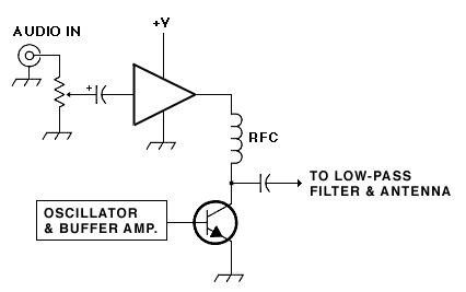
A line-level audio signal is fed to an audio amplifier I.C. The output of this chip is used as a power supply for the RF amp transistor.
This circuit is physically smaller and lighter than designs that use a modulation transformer. The audio quality is good.
Examples of technique #2B include the Vectronics 1290K kit and the Poppet transmitter, both of which use the LM386 amplifier chip.
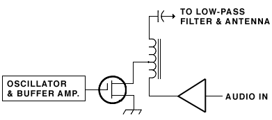
The RF output transistor is an FET (often an IRF510 or similar). The FET's source is grounded. The FET's drain is connected to a transformer, which has the modulation (audio) amp on one side and the RF output taken from the other side.
The Ramsey AM25 transmitter kit uses this technique. Its transformer is wound on a binocular ferrite core.
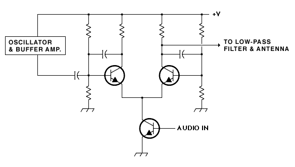
This is the system used in Charles Wenzel's circuit. This design has had many re-incarnations, for example in a proposed 13.5 MHz transmitter circuit. The Wenzel modulator is capable of high quality modulation at levels approaching 100%. For 100 milliwatt transmitters, suitable transistors are 2N4401 or 2N5551.
![]()
return to transmitter
building blocks page or Engineering
Dept.
![]()