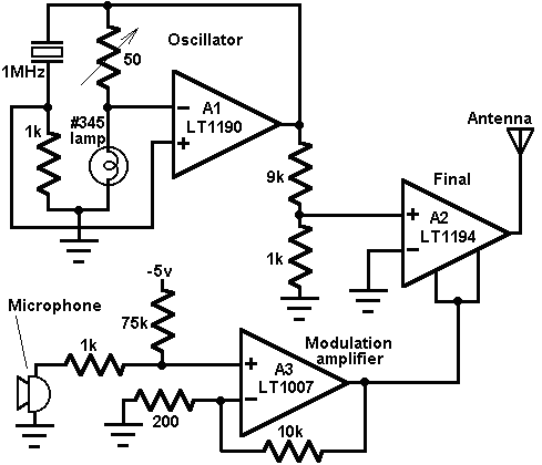


This circuit uses an LT1190, LT1007, and an LT1194 to form a AM radio transmitter. The carrier is generated by A1, set up as a quartz stabilized oscillator. A1's output feeds A2, functioning as a modulated RF power output stage. A2's input signal range is restricted by the bias applied to offset pins 1 and 8. A3, a microphone amplifier, supplies bias to these pins, resulting in an amplitude modulated RF carrier at A2's output. The DC term summed with the microphone biases A3's output to the appropriate level for good quality modulation characteristics. Calibration of this circuit involves trimming the 50 ohm potentiometer in the oscillator for a stable 1Vp-p 1MHz A1 output. The construction and operation of this apparatus may require Federal Communications Commission review and/or licensing.
Source: Linear Technology
Home | Product Info | Ordering Info | Contact Us | Get a Demo
Circuits in CyberCircuit | Circuits in CyberCircuit Plus | Circuit du Jour | Circuit Archive
Copyright (c) 1995-1998 by PTM