Easy Homebrew 2.4Ghz Omni Antenna
An easy step-by-step guide go making a
homemade wireless antenna, for a fraction of the cost of commercial antenna.
Uses readily available parts, and requires no specialist tools or knowledge.Or
in geek speak - an omnidirectional colinear dipole design suitable for wifi
compatible hardware with external antenna connector.
Most of the designs on the web for
2.4GHz
omni antenna seem to involve brass tubing and lmr-400 cable, none of which
are readily available to me. I then found a coax only design
for 444Mhz that was based on the same idea. The only reasonable cable I could
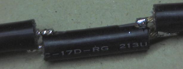
get my hands on was RG-213
from Maplin. By scaling the 444Mhz design
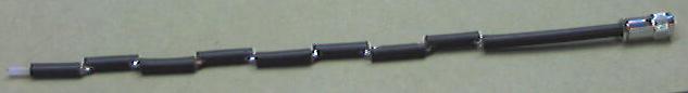
up to 2.4Ghz and using RG-213 I thought I'd have a go. In order to get about 6db
gain from the antenna, it would need 8 sectors, with a 1/4 wave section at the
top and a fly-lead with N-connector at the bottom. It should take about 2-3
hours to build an antenna using this design, but don't worry if it takes longer,
you will get quicker, especially as you only need to make the jig once.
Most of the designs
either had toroid magnets or a decoupler on the fly-lead of the antenna. However
the location of the decoupler seems different in each design, and some designs
quoted a decoupler length of 1/4 wavelength, others were !/4 wavelength times
the velocity factor of the decoupler tube (brass tube quoted at 0.95). I've
tried most locations and can report that without proper testing kit I can see no
difference in the Signal to Noise ratio between having a decoupler and not. I
decided to not bother as it simplified the design. If anyone knows a good reason
why you must have a decoupler then I would love to know (especially if
you know where it should be exactly). If you want to add a decoupler, please do,
I found using 15mm or 22mm copper tube and a 15mm or 22mm end stop made a good
design, just needing to be soldered together to get the right length, and a hole
drilled in the end of the end stop to fit the cable.
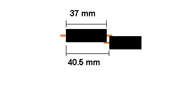
Each sector of the antenna needs to be a 1/2 wavelength long multiplied by
the velocity factor of the cable. The velocity factor of RG-213 is 0.66 . If you
decide to use different cable (such as LMR-400) then you need to get the
velocity factor of that cable (which will be different), and recalculate
all the dimensions.
                          V * C    0.66 * 299792458
        1/2 wavelength = ------  = ---------------- = 0.0405m  = 40.5mm
                          2 * F     2 * 2441000000

         V = Velocity  Factor   of  RG213  = 0.66
         C =  speed of light = 299792458
         F =   Frequency  of Signal =  2441000000 (mid  point of 2.4Ghz range)
The 1/4 wave element is not adjusted by the Velocity factor, as it is in the
open, so works out at just 31mm long giving a total antenna length of 355mm +
fly-lead. (Thanks to Oscar for correcting me of this.)
All of the parts are available cheaply from either Maplin and any diy
shop.
- 1m RG-213U cable (available by the meter from Maplin). This is enough for
2 antenna. Buy more for whatever flylead length you want.
- N connectors, Depending on what you want to connect to , use either male
or female connectors, and inline or bulkhead. Remember inline connectors need
to fit 10mm diameter RG-213 cable
- 20mm pvc conduit (available from any diy store) Has a 20mm inside
diameter, and 22mm outside.
- 22mm pipe clips (depending on how you want to mount the antenna), pipe
clips make it easy to mount and unmount, or use the proper conduit brackets
(but they seem a little expensive).
You don't need any special tools
- mm rule for measuring !
- junior hacksaw
- stanley knife
- pliers
- standard soldering iron (don't need a heavy duty one) and solder
- off cuts of wood to make a jig to aid soldering
- bench or vice to hold cable while you cut it
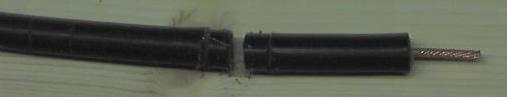
After much trial and error, I found that the neatest way to cut the cable is
actually with a junior hacksaw. It gives a much cleaner finish than wirecutters.
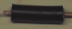
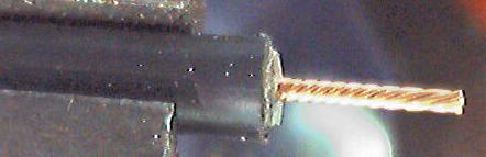
Each sector consists of a short length of RG-213 cable, with the central core
sticking out each end.
When building the antenna, the exact length of each piece of RG-213 is not
that important, it is the overall length of each sector that counts. I found
that cutting the cable to 37mm with 6mm of core sticking out each end, gets
enough overlap to easily solder the segments together. If you allow 1mm for the
width of the hacksaw when cutting the sectors apart, it means you need 37 +6 +6
+1 = 50mm of cable for each sector making 8sectors + 1/4wave section come to 420
mm of cable for the antenna + cable for the fly lead.
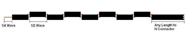
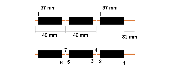
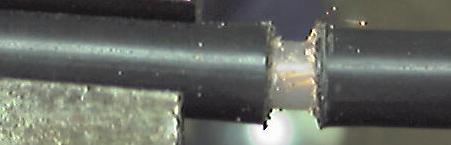
The best way to cut each sector is to make the cuts where each end of the
sheathed section of the sector will be, before making the cut between each
sector. The picture below shows the top 3 sections of the antenna, and the 1/4
wave section, showing the order that the cuts should be made.
The best way to make the cuts is to mark them out on the cable first. When
sawing the cable it has a tendancy to deform and bend, so lightly sawing round
the outside sheath first, but not cutting through, helps give a guide to the
cutting for real. I use the junior hacksaw to gently saw round the cable sheath
to make the mark for each section.
The first mark will be at 31mm from the end, which is for the 1/4 wave
section at the top. Once you have made the mark, it is time to cut round the
cable. You want to cut through the sheath, shielding, and just into the central
insulation, but not into the central copper wires. You may need to
practice a bit first, but you should be able to feel as you cut through the
shielding into the central insulation. By leaving plenty of sheathed section
either side of the cuts, the shielding stays in place when being cut.
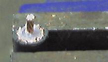
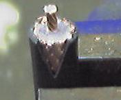
Now with pliers, gently twist off the end 31mm of sheath & shielding
This should leave the cenral insulator exposed. Using the stanley knife score
round through the central insulator, but not too hard, or you will cut the
central cable. Now twist off the insulation. You should be able to see the twist
in the central cable through the insulation, which will show you which way to
twist off the insulation, resulting in the central core twisting more
tightly.
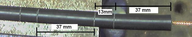
The next mark is 37mm down (68mm from end of the cable) and is the cut for
other end of the sheathed section of the top sector. The next mark is 13mm down
(consists of 6mm core from each sector and 1mm for cut between sectors) (81mm
from end) and is the top of the sheathed section of the second sector. The next
mark is 37mm down, then 13mm, then 37mm, and so on and so forth until you have
each of the sheathed sections marked out.
You can now start
making the cuts, remembering to only cut through the sheath, shielding and just
into the central insulation. First make the cut at 37mm down, then the next cut
a further 13mm down. You may find that some of the shielding pulls out when you
make this cut, as the 13mm length of sheath cannot hold the shielding tight
enough. Don't worry, it doesn't matter.
Now you are ready to cut off the top sector from the cable. You want to cut
through the whole cable at the mid point of the two cuts you have just made,
that is about 43.5 mm from the end of the sheath, or 74.5 mm from the end of the
cable. See position 4 in the diagram above. Just saw carefully the whole way
through the cable.
Now you can pull off
the sheath and shielding from the each end.
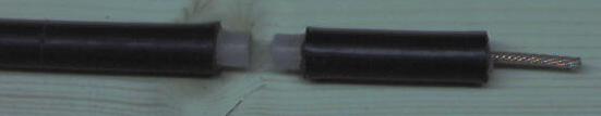
Now score round the
insulation as you did before, being careful not to cut the central cable
Now carry on making
cuts 37mm down from the end of the sheath, and then 13mm further down (50mm from
the end of the sheath), and then cut through the cable in the middle of the two
cuts. Another sector made. You will need eight sectors in total. Make the same
cuts as usual for the eighth sector as it will make top of the flylead as well.
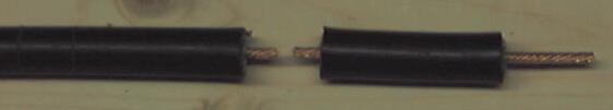
Now you have all eight sectors you need to check round the end of each sector to
make sure that none of the shielding is touching the central cable, as odd
strands can get left.
Now you need to make
a gentle V shaped cut with the stanley knife, at each end of the sectors, to
expose the shielding, which is where the central core of the next sector will be
soldered.
Make sure that the V
cuts at each end of the sector line up, othwise, when you come to solder the
antenna together, the whole thing will be twisted all around. Once you have all
eight sectors finished, its time to put them together.
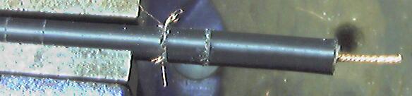
If you do not have a handy helper to
hold the sectors together, then you will find it easier to make a small jig from
offcuts of wood, to hold the sectors together as you solder them. The clamps on
the right hand side of the picture need to be no more than 30mm long. The base
board of the jig, needs to extend out to the right long enough to take the whole
length of the completed antenna, as it will need to support it during the
soldering, as the antenna is not rigid enough to support itself.
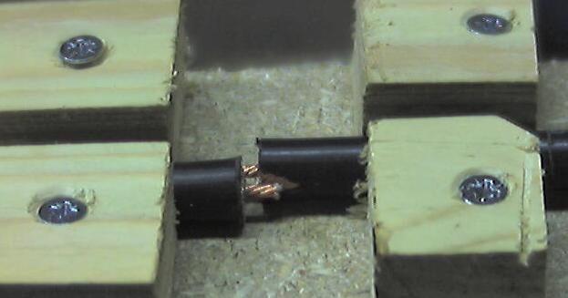
Don't make the
clamps too tight, as you need to be able to easily lift the cable out after it
has been soldered.
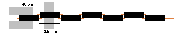
When you are readly to solder the sectors together, you need to take
care , that each sector is correctly spaced. The overall length of each
sector needs to be 40.5mm , measure from one end of the shielding of the sector
you are adding, to the same end on the next sector, and slide the sectors
together/apart until the distance is 40.5 mm. Try to get it as accurate as you
can, as it affects the direction the antenna transmits in if you get it wrong.
There should be a small 3mm gap between the sheaths of each sector.
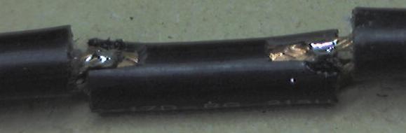
Once you have soldered each sector together, lift it up, turn it over, and
move it down the clamp ready for the next sector. This results in a nice
straight antenna. When soldering, remember to heat both the shielding and core
so that the solder runs smoothly and fixes them together.
Once complete, test the cable with either a bulb and battery or a multimeter.
The center of the fly lead should form a circuit to the 1/4 wave section, and
the shield of the flylead to the shield of the top section. Now test that there
are no crossed connections, by ensuring there is no circuit between the center
of the flylead and the shielding of the top sector, and no circuit between the
1/4 wave section and the shielding of the flylead.
Now fix the N connector of your choice onto the end of the fly lead. The type
of connector you use depends on what you want to connect to. I use inline
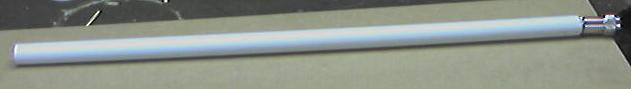
connectors, but you could use any connector you like. Slide the antenna into a
length of conduiting. It should be a snug fit, you may need to gently ease it
in. Now find an old soft drink bottle top, and pop it on the top end of the
antenna. Voila one complete antenna ! Securing the antenna in the conduit is
best left until you are ready to mount it somewhere. You can cut 5cm slots in
the bottom if the conduit, and use a jubilee clamp to grip the flylead, or drill
a hole through the conduit and use a cable tie to hold the fly lead, or use a
bulkhead mount connector on a botle cap, and glue it to the bottom of the
conduit, or glue the flylead in place. It's up to you.
I will assume you are connecting the antenna to a wireless card in a laptop,
and connecting to an accesspoint somewhere. You will need to a signal to noise
meter to examine the signal strength. Most wifi cards come with software that
does this. Now its time to test that the antenna actually works. This can be
harder than it sounds, as unless you can remove the existing aerial from the
card or ap, you can't tell it is using your new homebrew antenna. Well wrapping
the existing antenna completely in 6-8 layers of tinfoil, has a dramatic
reduction on signal strength, now connect the antenna, and the signal should go
back up. Remember that omni antenna send out the signal horizontally, so don't
test it from the room below your access point. Hopefully you should see that
your new antenna actually works. There are three ways to test the gain of the
new antenna
- Use spectrum analyser in a professional radio lab
- compare the gain of your new antenna, to the gain of a known antenna (Not
the pcmcia card)
- Carry out an empirical range test with your new antenna
If you
have access to a spectrum analyser I'd love to know your findings. If you have
an existing omni or yagi antenna, then you can compare the snr readings between
the two antenna. Remember to do the test outside, as bouncing the signal off
walls can really give odd results. Try to stand as far away from the antenna as
possible when doing the test, as even moving near it can change the results a
lot. Position the two antenna in the same place for the test. Don't try and
compare the snr of your new antenna to that of the wireless card in your laptop,
as just by turning the laptop round, or lifting it up, or holding it, can
dramatically change the snr. Try it and see what I mean. If you don't have
another antenna, then wander down your street until you are out of range. Now
wander back towards your AP, and wait for the laptop to chime that it has made a
connection. Note how far from home you are. Try it again, with the laptop
connected to the new antenna. Remember to keep the antenna vertical. I found
carrying them in a bag with the antenna poking out the top works well. Try not
to hold the antenna, as this will change the snr. You should now be able to pick
up your AP about twice as far away, assuming there are no new massive obstacles.
If you have a go at making this antenna, and get it working, drop me an email
(address at bottom of page) and let me know how you found building it, whether
you've found a simpler way, and ... be honest ... how long it took.
If you find that the antenna is not
working, then try tilting it towards the AP, as if the dimensions are wrong, it
tends to send the signal angled in a cone above and below the horizontal instead
of horizontally. If this is the case, check the dimensions. If it still doesn't
work, double check that the sectors are connected ok, and there are no crossed
connections. If all else fails make sure you are not connecting it to a 60ft
fly-lead as this will reduce the gain a lot.
- Wap-in-a-box : Attach a homebrew omni to a Medium Size
Waterproof case and then squeeze a WAP11 AP (out of its case) into the
box. Cable it up with Power-Over-Ethernet, and run the AP in "AccessPoint
Client" mode to extend the network with 'cheap repeaters'.
- Moonshine : Build a 32 element Omni (1.3m) and try to get 12db Gain
for longer range multipoint links (4km +).
I should point out now that I don't
claim that the above design is fit for any purpose, and don't accept any
liability for use of the design, or any antenna based on this design. If you
want to build an antenna using this design, then you are responsible for
ensuring that it doesn't breach any laws where you are, and is compatible with
any hardware you connect it to. If in doubt, buy a commercial antenna.

Last update 21st October
2002
